HOW TO tools in sketchup
I. DRAWING : 2D DRAWING TOOL

1. Line (L) – Line drawing tool.
- Enter L then left-click each point on the screen to draw the letter
- Move the mouse so that the line shows the colors Red - Green - Blue to select the direction // with the XYZ axis by locking the moving arrow keys
- Choose the method to enter the numerical value to get the correct length.
- Add the value and add units to get the length. (For example, 5m is equivalent to entering 3500)
- Press the ARROW keys to lock the direction along the X - Y - Z axis
- Hold SHIFT when you have selected a direction to temporarily lock the direction.
Additional function: Right click on the line
- Entity Info : Display and edit information
- Hide (H) : Hide the object.
- J : Show all
- K : Show the selected object is hidden.
- Soften : softens and hides edges.
- Table settings: + Smooth: Softens edges. + Soften coplanar: Hide coplanar edges.
- Divide : Equally divides edges.
[note]
- Instructions for Setting up sketchup when first installing
- Details of Setting parameters in Enscape
- Generic materials in Enscape
- Free sketchup course
[/note]
2. Freehand: Draw the line freely.
- Use the left mouse button to draw freehand lines (a tool that is rarely used)
3. Rectangle (R): Tool to draw a rectangle or square.
- To draw a rectangle accurately according to a specific size: Click to select a starting point and drag it to a certain position to make it easier to see, then enter the length. comma. comma width (note: each code has a different comma or semicolon).
- Press Ctrl to draw from the heart.
- For example: Draw a rectangle with a length and width of 1000×1000: If we enter (1000mm )
Additional functions: Right-click on the plane to have the following options:
- Select : All with same material : Selects all surfaces with the same material.
- Area : The area : + Selections : Area of the selected plane.
- + Material : Area of the material.
- Intersect faces : Create intersections between planes (Application: object intersection)
- Align View : Return the plane to planar projection (Camera à Parallel projection - Axial projection with 0 converging points).
- Align Axes : Return the coordinate origin to the plane corner à Align the point along the new edge and axis.
- Reverse faces : Reverse the plane.
- Orient faces : Reverses all other MPs in the direction of the selected MP. (Use more Frontface Plugin support right side reversing)
4. Rotated Rectangle: Draw an inclined plane. (useless)
- Select the starting point and the 0 degree plane - enter the length - drag the mouse to select the tilt direction - enter the width and tilt angle (note the value box)
- When entering width and tilt angle: Press the Alt key to select the 0 degree plane at any position.
5. Circle (C) – Draw a circle.
- Enter command C - Drag to a certain location and then enter the radius.
- If you want to enter an additional number of edges, enter C and enter the number of edges plus S + radius size
- + Where S is the number of edges of the image (The larger the number of edges, the smoother the image, but cannot be larger than 999)
Additional functions: Right click on the circle:
- Divide: divides the circle evenly into many equal arcs.
- Explode curve: Breaks the curve into discrete edges.
6. Polygon: Draw regular polygons. (rarely used due to use with Circle)
- Usage is identical to the circle. Press Ctrl to convert the inscribed polygon to circumscribed.
7. Arc: Draw an arc knowing Center - Radius - Angle measure. (useless)
- Select 1 start point and 1 end point then enter the arc radius
2 Point Arc (A) – Draw an arc knowing Chord – Height of the arc. (often used)
- Add the letter R next to the height value to convert to radius.
8. 2 Point Arc: Draw an arc passing through 3 points (rarely used)
Pie : Draw a sector knowing Center - Radius - Angle measure.
- Draw a closed arc: Select the starting point to enter the size and then enter the number of degrees
Save idea :
- Conclude end command draw Any object can still re-enter the most recent corresponding value.
- All roads round, sugary curved are all there sports number change edge is to enter nS (n is the number of sides of the circle or curve)
- The object muscle copy 2D above Have can check check and replace change information information in the Entity Info tabler.
II. PRINCIPAL: ESSENTIAL TOOL

1. Select (Space – space bar): Select the object.
- Sweep the mouse from left to right: Select objects within the selection area.
- Sweep the mouse from right to left: Select objects within and intersecting the selection area.
- Click 1: Select a single object.
- Click twice:
- + Edge up: Select an edge and the plane created from that edge.
- + Go to plane: Select that plane and surrounding edges.
- + Go to Group or Component: Access inside that Group and Component to edit.
- Click 3 times: Select all edge and plane objects that are connected
- Combined with keyboard shortcuts:
- + Hold Ctrl: Add selected object.
- + Hold Shift: Add and subtract selected objects.
- + Hold Ctrl + Shift: Subtract selected objects.
- + Ctrl + A: Select all.
- + Ctrl + T: Cancel selection (or point the mouse to an empty area).
2. Make component (G): Create a group of objects with the same properties.
- Select the object and then press the key
- The setup panel appears:
- + Definition: Name the component or not (Set if necessary).
- + Description: Description for the component (not necessary)
- + Set Component Axes: Reset the coordinate axis for the component (Set if necessary).
- + Always face camera: Creates a component with a surface always facing the screen.
- (Condition to select a surface that always faces the screen: The coordinate axis must have the X axis parallel to that surface, and the Y axis pointing back)
- Replace selection with component: Separate objects that share the same edge (always remember to integrate).
Additional functions Right-click on Component:
- Make Unique: Separate 1 or more components into a new group.
- Explode: Decompose layers.
- Components should be used more because the management features are more convenient.
3. Paint Bucket (B): Material pouring tool.
- Press the letter B on the keyboard > select the material panel to the right of Metarial then select pour over the material
4. Eraser ( E ): Eraser tool
- Hold Ctrl: Soften edge
- Hold Shift: Hide edges.
III. EDIT : EDITING TOOLS

1. Move ( M ): Move the object.
- Select the object to move - enter M - select the move point - select the destination.
- Press the arrow keys to lock the direction of movement along the X - Y - Z axis.
- Hold Shift when you have selected a direction to temporarily lock the direction.
- Once you have chosen the direction, you can capture points or enter the distance to move.
- Press Ctrl to copy the object.
- + Enter nX when you have finished copying the first object to multiply n additional objects in line outside the sequence.
- + Enter n/ when you have finished copying the object from the beginning of the range to the end of the range to divide the objects evenly in the range.
- When moving a point or plane, if the direction is locked, press the Alt key to cancel.
2. Push/Pull (p): Push the plane into a cube.
- You can select the plane first and then enter the P command to stretch and compress → Can only operate on that one surface.
- You may not need to select a plane first, enter the P command to compress and compress → Can operate on any surface.
- + Compression method 01: Hold and move the left mouse button on the surface that needs to be compressed.
- + Compression method 02: Click 1 time to select face - Click 2 times to determine destination (or enter distance)
- Compress the plane to the final position of the block to chisel the block.
- Double click to compress according to the previous value.
- Press Ctrl to copy the old plane.
- Press the Alt key to translate the plane according to its normal direction (in case the plane is not perpendicular to its surrounding surfaces).
3. Rotate (Q): Rotate – Rotate the object.
- Select object – enter Q – select center and plane of rotation – select grip point – move mouse select rotation direction – enter degrees
- If there is no rotation plane:
- + Press the Right - Left - Up - Down arrow keys to lock the plane's direction of rotation along the X - Y - Z axis
- + Hold and move the left mouse button in the direction of the rotation axis and then release to fix the rotation axis.
- While recording, press Ctrl to copy:
- + Enter nX when you have finished copying the first object to multiply n radial objects outside the arc.
- + Enter n/ when you have finished copying the first object to multiply n radial objects inside the arc.
- If the edge or plane is rotated, it will create a twisting phenomenon.
4 .Follow Me: Follow the link
- Select path → select command → select section (If the section is a Group or Component, right-click on it, select edit and then point to the section).
- The cross section must usually be placed perpendicular to the path.
5. Scale (S): Tool to change size.
- Select the object then enter S - select the blue grip points to drag.
- + If you drag a corner point: Zoom in all directions at the same ratio.
- + If you shrink and drag an edge point: Zoom in 2 dimensions corresponding to that edge.
- + If you stretch a face point: Stretch the object in one direction.
- Hold Ctrl to zoom from the center.
- Hold Shift to convert the zoom ratio of dimensions from general to private or vice versa.
- Units can be added next to the scale value to convert to total length.
6. Offset (F): Copy plane uniformly.
Select the object that needs offset then enter F (or enter F then select the object that needs offset) → move the mouse to select the offset direction → enter the distance.
[note]
- Instructions for Setting up sketchup when first installing
- Details of Setting parameters in Enscape
- Generic materials in Enscape
- Free sketchup course
[/note]
IV. CONSTRUCTION : CONSTRUCTION TOOLS

1. Dimensioning Tool (T):
- Click on the two ends of the line to measure the size.
- Click on 1 end of the line segment and 1 point outside to create an endpoint.
- Click on a point on the edge to align the line // (double-click on the edge of the line to coincide with the edge.
- Measure the size of an edge then enter a new size to zoom the entire object according to that edge as a standard (go into Group or component to zoom an individual object.). This function is often used for drawing image files or PDFs.
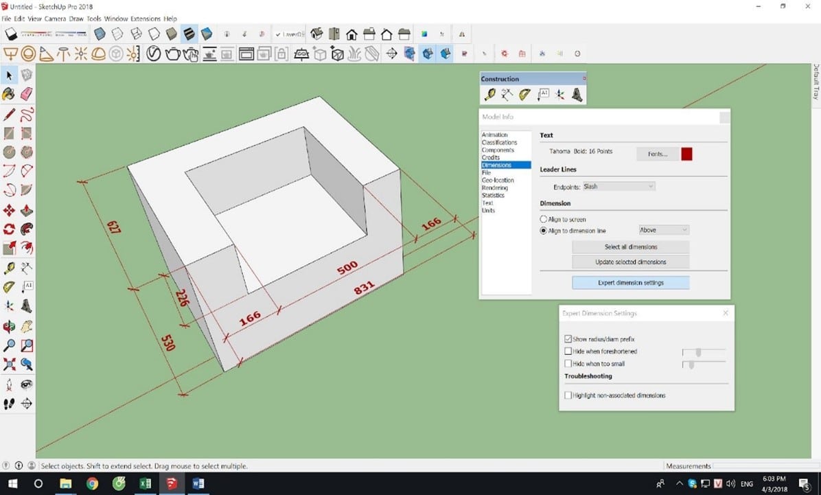
2. Record dimensions.
Click on any 2 points and drag them out to record the size.
- Go to the Model info / Dimensions panel to set up notes.
- Expert setting dimension: Invisible setting
- +Hide when foreshortened: Hide and show Dim according to perspective.
- +Hide When too small: Hide and show Dim according to size.
3. Angle Measurement tool.
- Practical activities in class.
- Application to create slope according to normal Angle value: Perform angle measurement as usual – > In the second angle selection operation, enter the slope angle value.
- % slope creation application: Perform angle measurement as usual – > In the second angle selection operation, enter X : Y (X and Y are the % ratio) eg (20:100) (2:10) (1 :5)
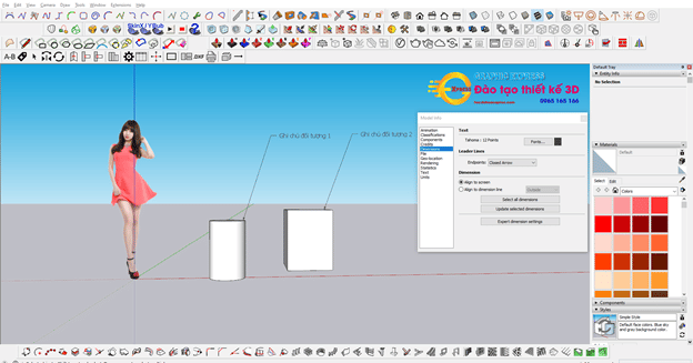
4. Note the object.
5. Coordinate axis conversion tool .
- Right-click on the coordinate axis to add more options.
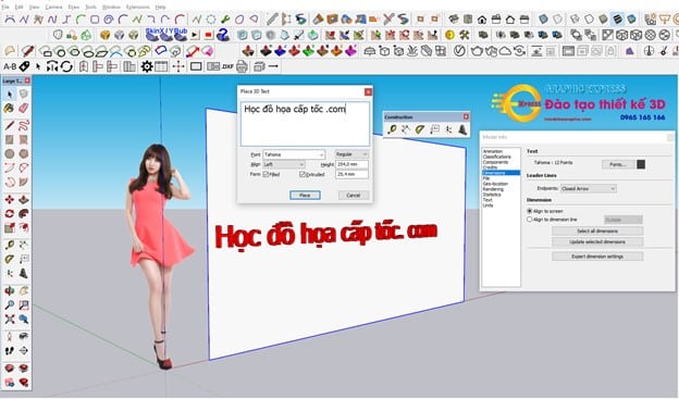
6. 3D Text Creation Tool.
- You just need to select the 3D tool then enter the text you want to include.
- Note: This tool does not have a text editing function, so you should type it properly before inserting it
V. CAMERA in Sketchup: View control tool

1. Orbit (Middle mouse) : Rotate the frame.
+ Hold Ctrl + middle mouse button: Rotate freely. (use the mouse for convenience)
2. Pan (Shift + middle mouse): Tool to move the screen.
3. Zoom (India Z then move the left mouse button or ROLL MOUSE): Zoom far and near the frame.
- Press Z and then enter parameters to change the CONTAMINATION of the lens (Perspective suction) (Z set from 35 to 50 corresponds to the eye)
- Go to Camera/Field of view: Then move the left mouse up and down to increase or decrease the lens focus without jumping the camera angle.
4. Zoom window (Ctrl + Shift + W): Zoom in tightly
- Use the left mouse button then scan some selected areas. The system will zoom to the correct location you are selecting
5. Zoom extents (Shift + Z): Zoom the entire object onto the screen.
6. Previous (Alt + Z): Return to the previous perspective.
- Alt + X: Move forward in perspective.
7. Position Camera :
Left click to set the observer's position.
8. Look Around: Move the left mouse button to observe the eyes.
+ Enter parameters to change eye height. Usually from 1m6 - 1m8
9. Walk: Move the left mouse button to move your steps
+ Hold Shift + left mouse button to change the height when moving
10. Zoom Selection (Right mouse button and press Z): Zoom the object tightly onto the screen.
Epilogue
So through this article, I have guided you in detail Use tools in Sketchup. Through this article, we hope you will understand more details about this software.
If you are someone who has never used sketchup before, you can refer to it. Sketchup course from basic to advanced of Graphic Express. Sketchup course 1-on-1 training. Hands-on instruction. Horizontal arms can also be done easily after this course.
Good luck


